Характеристики товара
1. The millimeter wave radar has a measurement accuracy of up to ±1mm, and the measurement blind area is 10-50mm.
2. Smaller antenna size to meet more working conditions.
3. Multiple lens antennas, 3° emission angle, more concentrated energy, stronger echo signal, higher reliability than other radar products under the same industrial and mining conditions.
4. It has stronger penetration and can be used normally even in the presence of adhesion and condensation.
5. The dynamic signal range is larger, and the measurement of low dielectric constant media is more stable.
6. Multiple measurement modes, radar response time is less than 1S in fast measurement mode.
Product advantages

Параметры продукта
|
measuring principle
|
2 / 4 wire, FMCW radar
|
|
frequency range
|
W-band [76-81GHz]
|
|
maximum operating range
|
The maximum is 120 meters
|
|
certainty of measurement
|
±1mm
|
|
output form
|
4~20mA,RS-485
|
|
communication mode
|
HART,MODBUS
|
|
Power supply range
|
24±6V
|
|
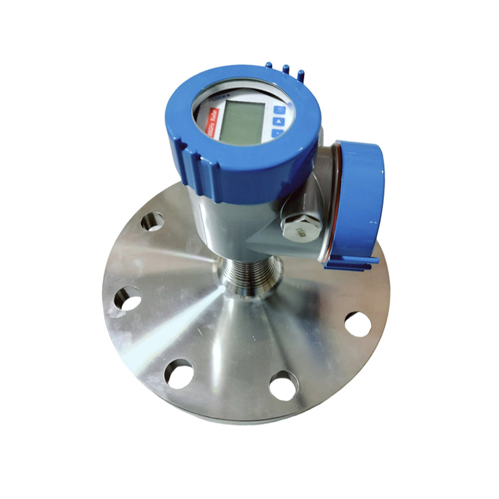
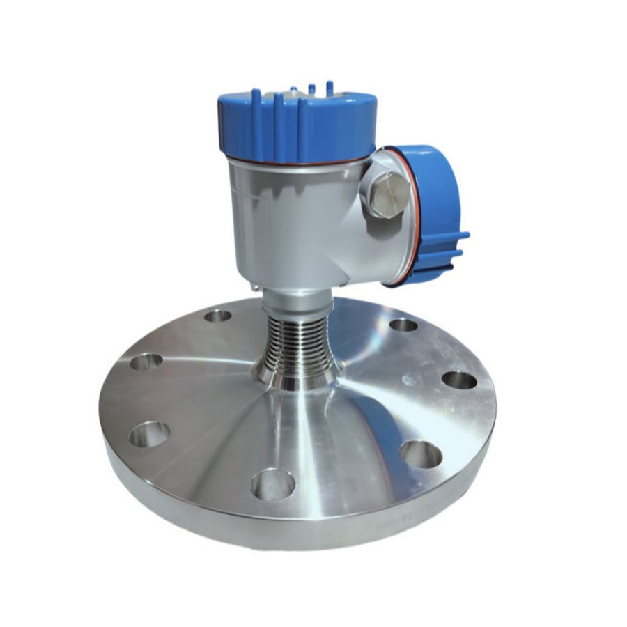
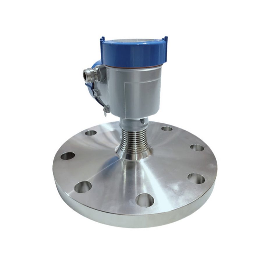
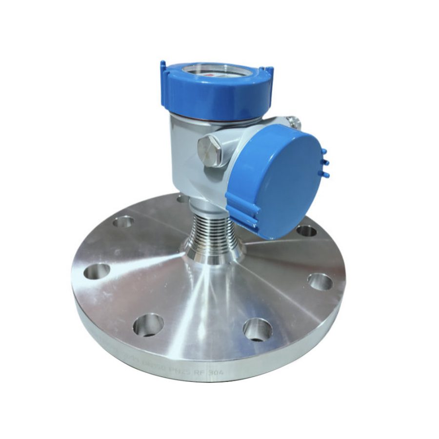
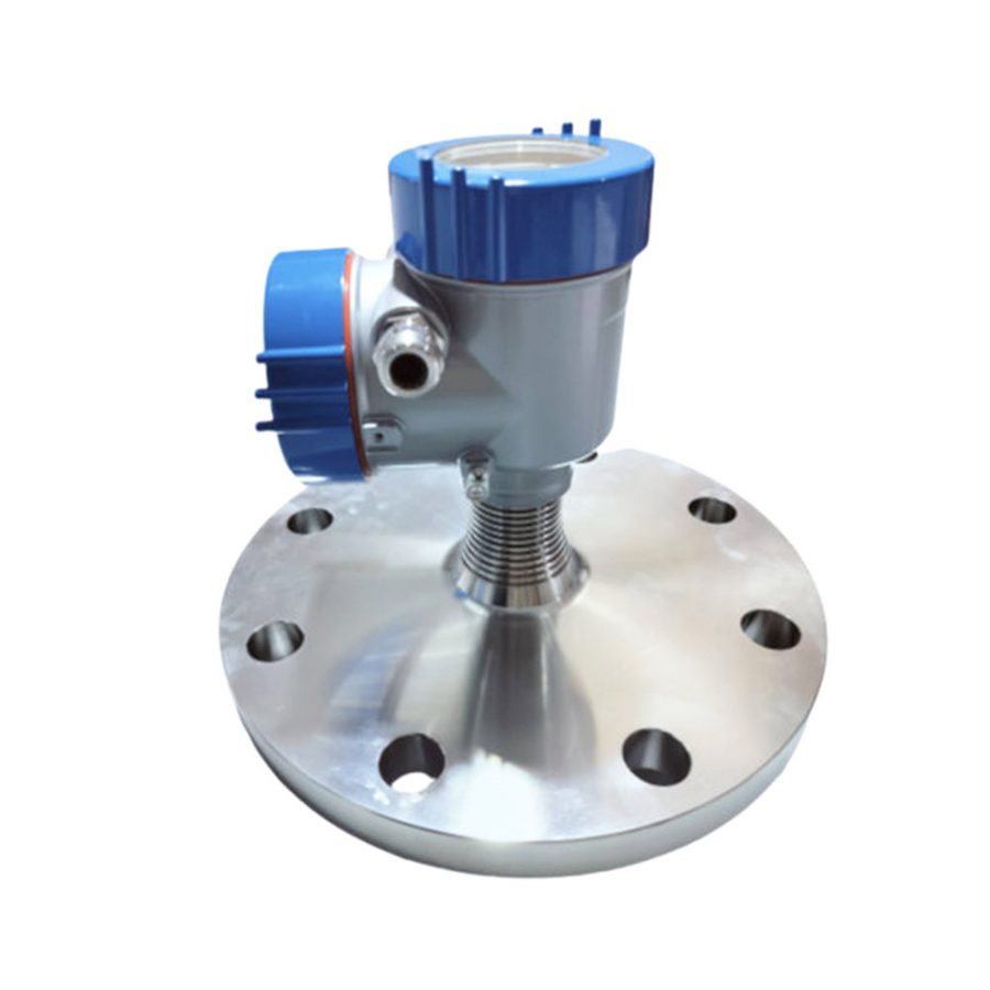
Antenna form
|
Horn or lens antenna
|
|
Process joint
|
Flange starts from DN50 and thread starts from G3 / 4
|
|
Давление процесса
|
-1…20 bar
|
|
Температура процесса
|
-40~+200℃
|
|
Environmental storage temperature
|
-40~+80℃
|
|
incrustation
|
Casting aluminum / stainless steel
|
|
Seal between the housing and the housing cover
|
silicon rubber
|
|
Case window
|
polycarbonate
|
|
earth terminal
|
stainless steel
|
|
Cable inlet / plug
|
1 blind block M20×l.5/1 M 20xl.5 cable inlet
|
|
connecting terminal
|
Lead cross-section is 2.5mm²
|
|
breakdown signal
|
Current output is unchanged;21mA;3.6mA
|
|
integration time
|
(0~20)s,tunable
|
|
fade zone
|
0.05m/0.2m
|
|
Measurement interval
|
About 1 second (depending on the parameter settings)
|
|
governing time
|
About 1 second (depending on the parameter settings)
|
|
relative humidity
|
˂ 95%
|
|
shatter-proof
|
mechanical shock l0m/s² , (10~150)Hz
|
|
Уровень защиты
|
IP67
|
|
anti-hazard classification
|
ExdiaIICT6
|
|
way to install
|
Threaded or flange
|
Installation method 1: Threaded installation

Installation method 2: Flange installation
When flange installation is used, the minimum distance between the instrument and the tank wall should be 200mm
① Reference surface ② Center of container or symmetry axis

Installation method 3: Hoisting
(select according to specific installation conditions)