Обзор
Реле потока TFS-800 - это измерительный прибор, который может контролировать поток жидкости в трубопроводе в режиме реального времени и выдавать сигнал на выходе. Этот продукт имеет полностью металлический корпус, не имеет движущихся частей, количество переключателей может быть непрерывно отрегулировано на месте, потеря давления мала, структура компактна, и несколько светодиодов отображают состояние потока и состояние переключателя в режиме реального времени. Он прост в установке и подходит для труб различного диаметра. Он может использоваться для контроля скорости потока жидкости в трубопроводе, мониторинга прерывания потока или предотвращения защиты насоса от холостого хода. Он широко используется в гидроэнергетике, промышленной гидравлике и других местах, где необходимо контролировать скорость потока жидкости в трубопроводе.
Параметры работы
Диапазон измерений: 1~150 см/с (вода), 3 см/с~300 см/с (масло)
200~3000 см/с (газ)
Рабочее напряжение: 24±20%VDC;
Ток потребления: <90 мА;
Сигнальный выход: реле (SPDT), транзистор PNP;
Коммутационное напряжение: 24±20%VDC;
Ток переключения: ≤1,2A;
Коммутационное напряжение: ≤250VAC/30VDC;
Ток переключения: ≤3A;
Время инициализации: Типичное значение 8 с (2~15 с);
Время отклика: Типичное значение 2 с (1~15 с);
Температурный градиент: Верхний предел 250℃/мин;
Степень защиты: IP67
Температура среды: -20~80℃;
Температура окружающей среды: -10~70℃;
Температура хранения: -20~85℃;
Номинальное давление: 10 МПа;
Материал зонда: 304 нержавеющая сталь
Материал корпуса: 304 нержавеющая сталь
Применение продукта
В этом изделии интегрированы чувствительный элемент и блок обработки сигнала. Настройка контроля расхода непрерывно регулируется. Диапазон контроля связан с расходом, но не с расходом или общим расходом. Данное устройство используется для следующих функций контроля:
(1) Средний расход/пониженный расход;
(2) Среднее присутствие/отсутствие;
(3) Средний поток/стационарный.
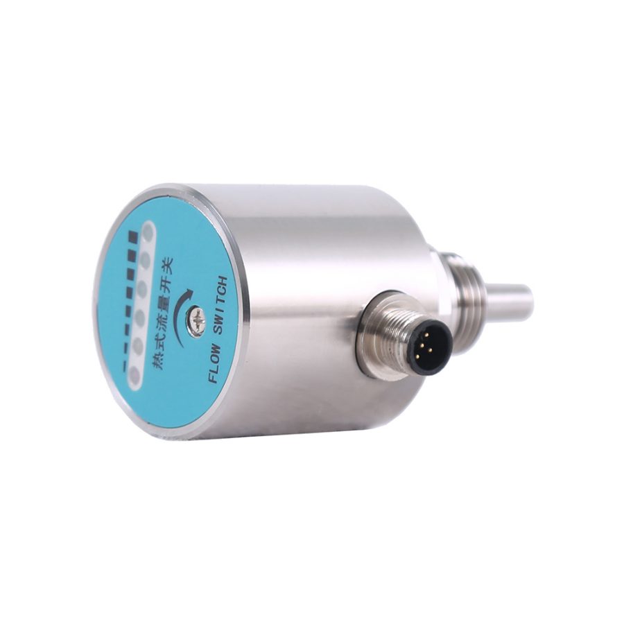
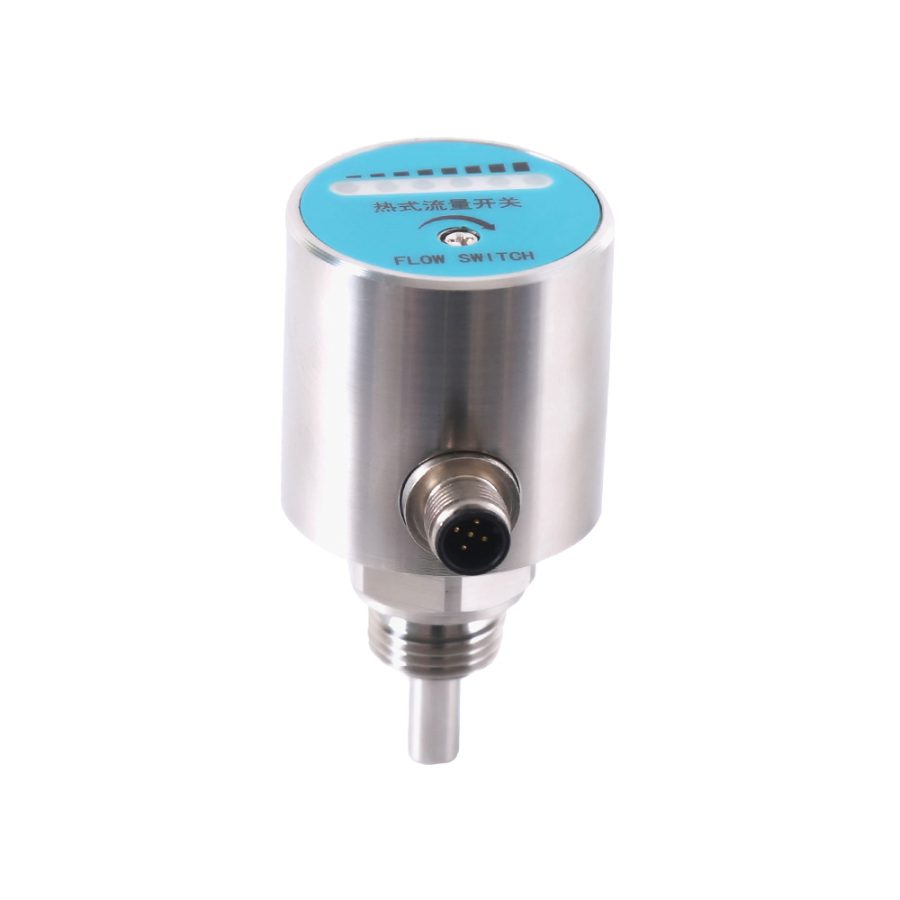
Этот продукт использует 6 разноцветных индикаторов, расположенных в ряд на панели, для отображения состояния тревоги и динамики расхода, и выводит сигнал переключателя через одно реле. Значения 6 индикаторных лампочек следующие:
1 красный индикатор: если он горит, значит, заданный расход не достигнут;

1 желтый индикатор: когда он горит, заданный расход достигнут/превышен, и реле начинает работать;

4 зеленых индикатора: Когда скорость потока превышает установленное значение, они загораются последовательно. Чем больше лампочек горит, тем больше расход. При уменьшении расхода они гаснут в обратном порядке.

Структура внешнего вида и электрическое определение
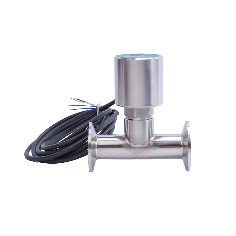
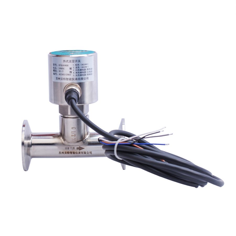
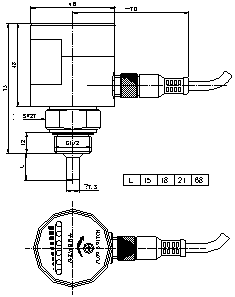
Реле расхода подключается с помощью кабеля или разъема. Его внешний вид показан на рисунке 1.
Чертеж со структурными размерами:
Электрическое определение: Авиационный штекер M12*1
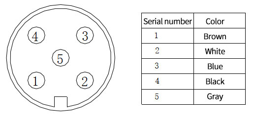
Таблица 1 Электрическое определение
Ответственность
В течение одного года с момента отгрузки наша компания бесплатно заменит или отремонтирует продукцию с дефектами качества, вызванными проблемами материала и изготовления; в случае поломки продукции, вызванной некачественными причинами во время использования, наша компания будет нести ответственность за ремонт и взыскивать только материальные затраты.

