Working Principle
LZB/ LZG series of glass rotameter is widely applied in chemical engineering, petroleum, light industry, medicine, environment protection, food, measurement and test, scientific research and other departments and used to measure the flows of single-phase non-pulsating fluid (liquid or gas).
LZB/()F/LZJ-()F series of corrosion-resistant glass rorameter has a strong corrosion resistance, can be used to measure the flows of acid(except for hydrofluoric acid), alkaline, oxidizing agent and other corrosive gas or liquid and is suitable for chemical engineering, pharmacy, paper making, sewage treatment and other industries.
Product features
Table 1 unit: mm
Drift
diameter DN |
A |
B |
C |
D |
E |
Type of connection |
| 4 |
178 |
204 |
230 |
10 |
38.5x33(fro nt) |
Flexible pipe |
| 6 |
178 |
204 |
230 |
10 |
42x33(fron t) |
Flexible pipe |
| 10 |
95 |
208 |
244 |
12 |
45x40(fron t) |
Flexible pipe |
| 15 |
115 |
65 |
470 |
15 |
4-14 |
Flange |
| 25 |
110 |
85 |
470 |
25 |
4-14 |
Flange |
| 40 |
145 |
110 |
570 |
40 |
4-18 |
Flange |
| 50 |
160 |
125 |
570 |
50 |
4-18 |
Flange |
| 80 |
185 |
150 |
660 |
80 |
4-18 |
Flange |
| 100 |
205 |
170 |
660 |
100 |
4-18 |
Flange |
Notes: flange standards GB/T119-2000 DN(15-50), DN(125-150) PN1.0MPa
DN(80-100) PN0.6MPa

| Hold-down nut |
| sensor |
| Cable |
| Regulating nut |
| With alarm switch |
| Wiring |
| Notes: the conventional output signals of alarm switch arePNP and NPN signals, which should be mentioned when placing an order. |
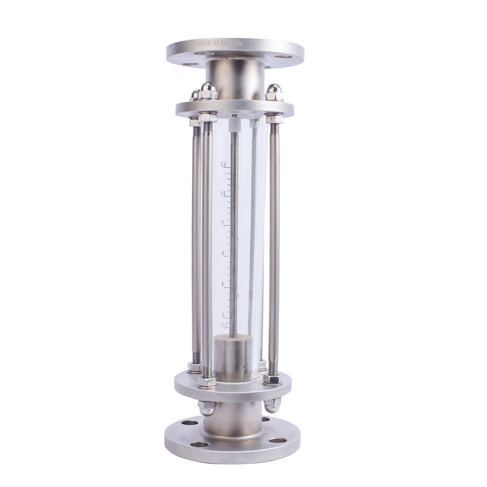
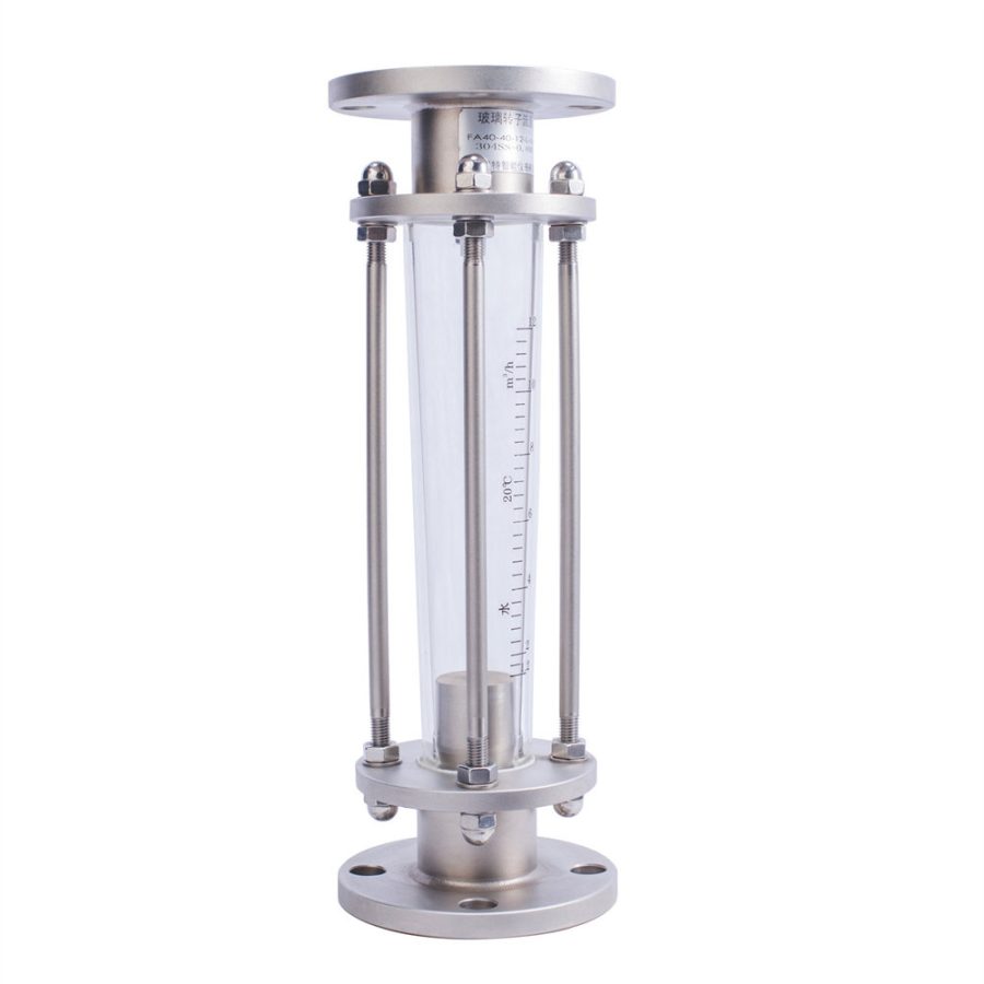
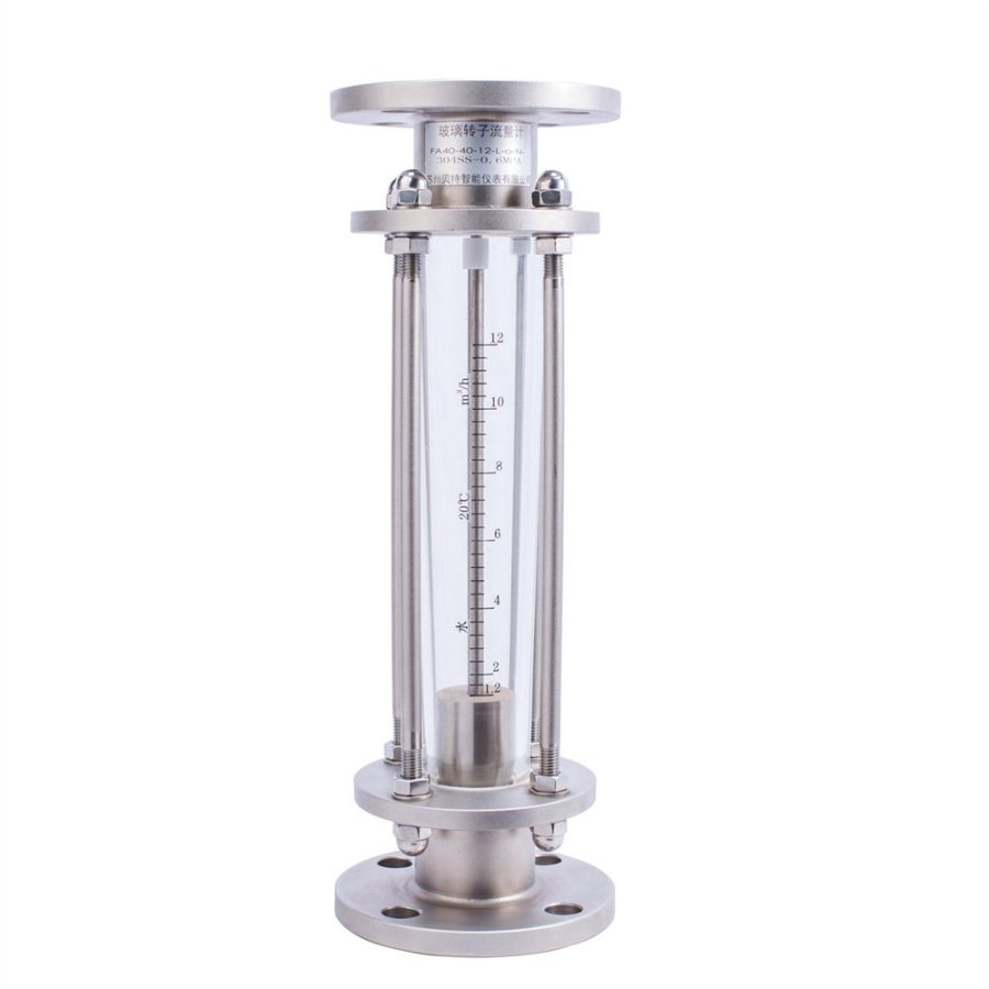
Principle and structure
Flowmeter consists of a subuliform glass tube expanding from bottom to top and a floater moving up and down with the change of flow of fluid (Fig 3). When fluid flows through subuliform from bottom to top, the lift force S produced by fluid kinetic energy and the floatage A of fluid make floater rise. When the sum of lift force and floatage is equal to the gravity G of floater, floater is in a stable state and located at a height and the scale on subuliform glass tube indicates the flow of fluid.
The position of floater in flowmeter is shown in Fig 4.

Fig 3
| Floatage |
| Lift force |
| Gravity |
| reading |

| Columniform floater at sharp edge |
| Ball-shaped floater |
| Reading |
The subuliform tube of LZB/LZB-()F flowmeter has a smooth internal wall (shown in Fig 5). For the flowmeters with the drift diameter of DN 15 and above, floater moves up and down and keep stable through guide rod. There are three guiding element rests on the internal wall of subuliform tube of LZJ/LZJ-()F flowmeter which keep floater stable (shown in Fig 6). Flowmeters with DN10 and below are connected through flexible pipe and equipped with aciform regulating valve; the flowmeters with DN15 and above are connected through flowmeters.