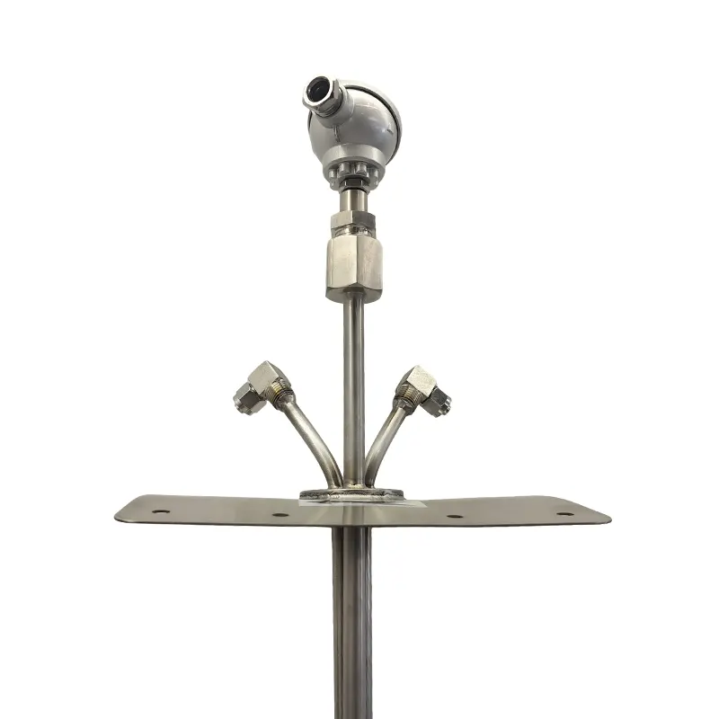
The PT1 series Pitot tube flow meter is suitable for measuring the velocity of media such as steam, liquid, air, and gas in pipes. It is especially suitable for measuring the velocity of large-diameter ducts. It features reliable principle, simple structure, and low cost, making it an ideal flow detection instrument for online monitoring systems of industrial boiler gas emissions.
See Figures 1, 2, and 3. The installation quality of the Pitot tube has a significant impact on its measurement. Since the Pitot tube flowmeter operates based on the theory of stable fluid flow within a filled circular tube, the measurement point should be located away from components that easily cause flow fluctuations, such as fans, valves, and elbows. Furthermore, there should be a 3D to 5D straight pipe section upstream of the measurement point to ensure that the velocity distribution across the flow cross-section at the measurement point meets the requirements. The Pitot tube uses an insertion-type installation; therefore, the axes of the total pressure and back pressure taps must be coplanar with the geometric symmetry center axis of the pipeline, ensuring that the total pressure measuring hole faces the incoming flow. The installation orientation of the Pitot tube flowmeter on the pipeline is: the axis of the insertion protection pipe should be perpendicular to the geometric symmetry center axis of the pipeline. Incorrect installation orientation will significantly increase the uncertainty of the Pitot tube instrument coefficient C. Users are advised to measure the relevant dimensions of the installation point before installation for adjustment to ensure the Pitot tube installation meets the requirements.
**Output Method and Impedance Matching**
a. The differential pressure transmitter outputs a 4-20mA differential pressure proportional current signal; output mode: two-wire.
b. The DC power supply ripple should be less than 2%. The total power load is equal to the sum of the sampling resistor, signal line resistance, and the load resistance of the relevant controller in the loop. Note that if an intrinsically safe barrier is used, the barrier resistance must be included. The power load limit is calculated using the following formula:
RL = (V1—)L
Where: RL---------- Maximum loop resistance; V--Power supply voltage
Please carefully check all the above points before wiring. Any accessories and interface devices that do not meet the requirements must not be connected to the instrument to avoid damage.
Instrument Wiring
Instrument wiring is essentially differential pressure transmitter wiring, as shown in Figure 4. Please refer to the instruction manual to connect the power supply and load to the corresponding signal output terminals. Do not connect to the two terminals marked "test" or short-circuit the wiring. Any short circuit may cause the instrument to burn out, data loss, or program corruption! After confirming that the wiring is correct, you can connect the power supply for use.