- Home
- Products
-
Flow Measurement
Pitot Tube Flow Meter Variable Area Flow Meter Electromagnetic Flow Meter Vortex Flow Meter Liquid Turbine Flow Meter Gas Turbine Flow Meter Glass Rotor Flow Meter Plastic Rotameter Coriolis Mass Flow Meter Thermal Mass Flow Meter Ultrasonic Flowmeter Panel Flowmeter Miniature Variable Area Flowmeters Gear Flow Meter Positive Displacement Gear Flow Meter Impeller Flow Meter Precession Vortex Flowmeter Orifice Flow Meter Annubar Flow Meter Baffle Flow Meter High Pressure Rotor Flowmeter Plastic Body Rotor Flowmeter Constant Current Device Constant Flow Valve Magnetic Filter
- Level Measurement
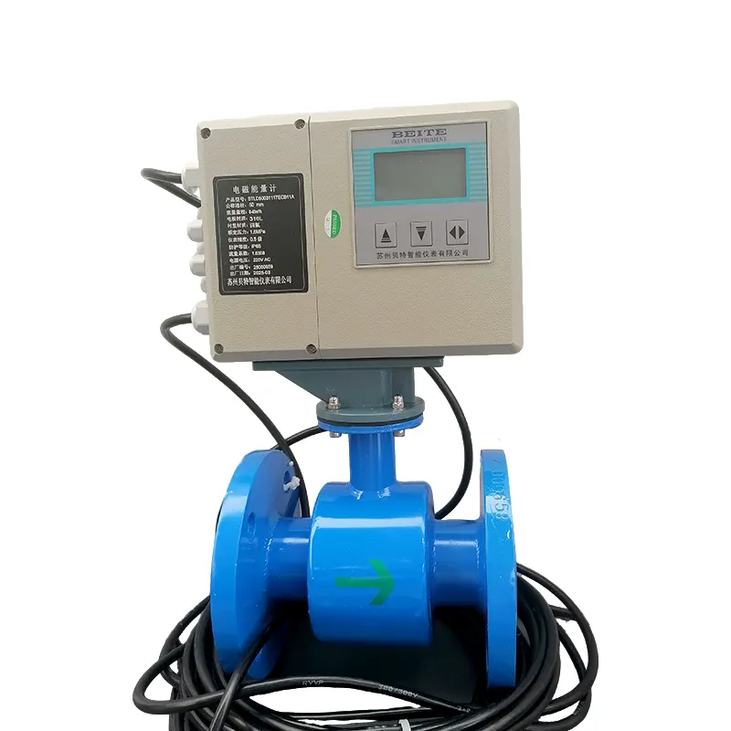
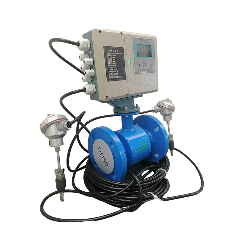
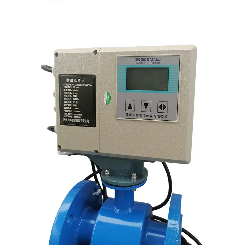
- Pressure Measurement
- Temperature Measurement
- Display Instruments
- Flow Switch
- Visual Sight Indicator
- Atmospheric Environment Monitoring
-
Flow Measurement
- About Us
- Solution
- News
- Contact