Overview
TFS-800 flow switch is a measuring instrument that can monitor the flow of liquid in the pipeline in real time and provide signal output. This product adopts a full metal shell, no moving parts, the switch quantity can be continuously adjusted on site, the pressure loss is small, the structure is compact, and multiple LEDs display the flow state and switch state in real time. It is easy to install and the product is suitable for various pipe diameter requirements. It can be used to monitor the flow rate of fluid in the pipeline, flow interruption monitoring or prevent the pump from idling protection. It is widely used in the hydropower industry, industrial hydraulic industry and other places where the flow rate of pipeline fluid needs to be monitored.
Performance parameters
Measuring range: 1~150cm/s (water), 3cm/s~300cm/s (oil)
200~3000cm/s (gas)
Working voltage: 24±20%VDC;
Consumption current: <90mA;
Signal output: relay (SPDT), PNP transistor;
Switching voltage: 24±20%VDC;
Switching current: ≤1.2A;
Switching voltage: ≤250VAC/30VDC;
Switching current: ≤3A;
Initialization time: Typical value 8s (2~15s);
Response time: Typical value 2s (1~15s);
Temperature gradient: Upper limit 250℃/min;
Protection level: IP67
Medium temperature: -20~80℃;
Ambient temperature: -10~70℃;
Storage temperature: -20~85℃;
Pressure rating: 10MPa;
Probe material: 304 stainless steel
Shell material: 304 stainless steel
Product application
The sensing component and signal processing unit of this product are integrated. The flow rate monitoring setting is continuously adjusted. The monitoring range is related to the flow rate, but not to the flow rate or overall flow rate. This product is used for the following monitoring functions:
(1) Medium flow/reduced flow rate;
(2) Medium presence/absence;
(3) Medium flow/stationary.
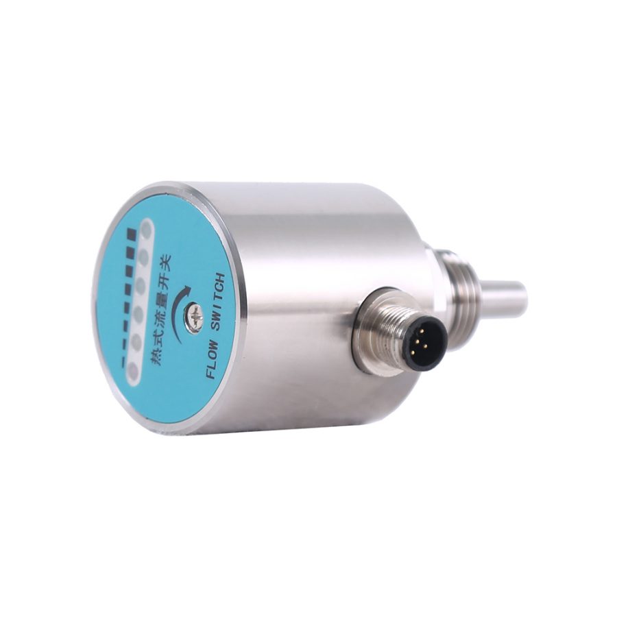
This product uses 6 different colored indicator lights arranged in a row on the panel to display the alarm status and flow rate trend, and outputs the switch signal through a single relay. The meanings of the 6 indicator lights are as follows:
1 red indicator light: when it is on, the set flow rate has not been reached;

1 yellow indicator light: when it is on, the set flow rate is reached/exceeded, and the relay starts to operate;

4 green indicator lights: When the flow rate exceeds the set value, they light up in sequence. The more lights on, the greater the flow rate. When the flow rate decreases, they go out in the opposite order.

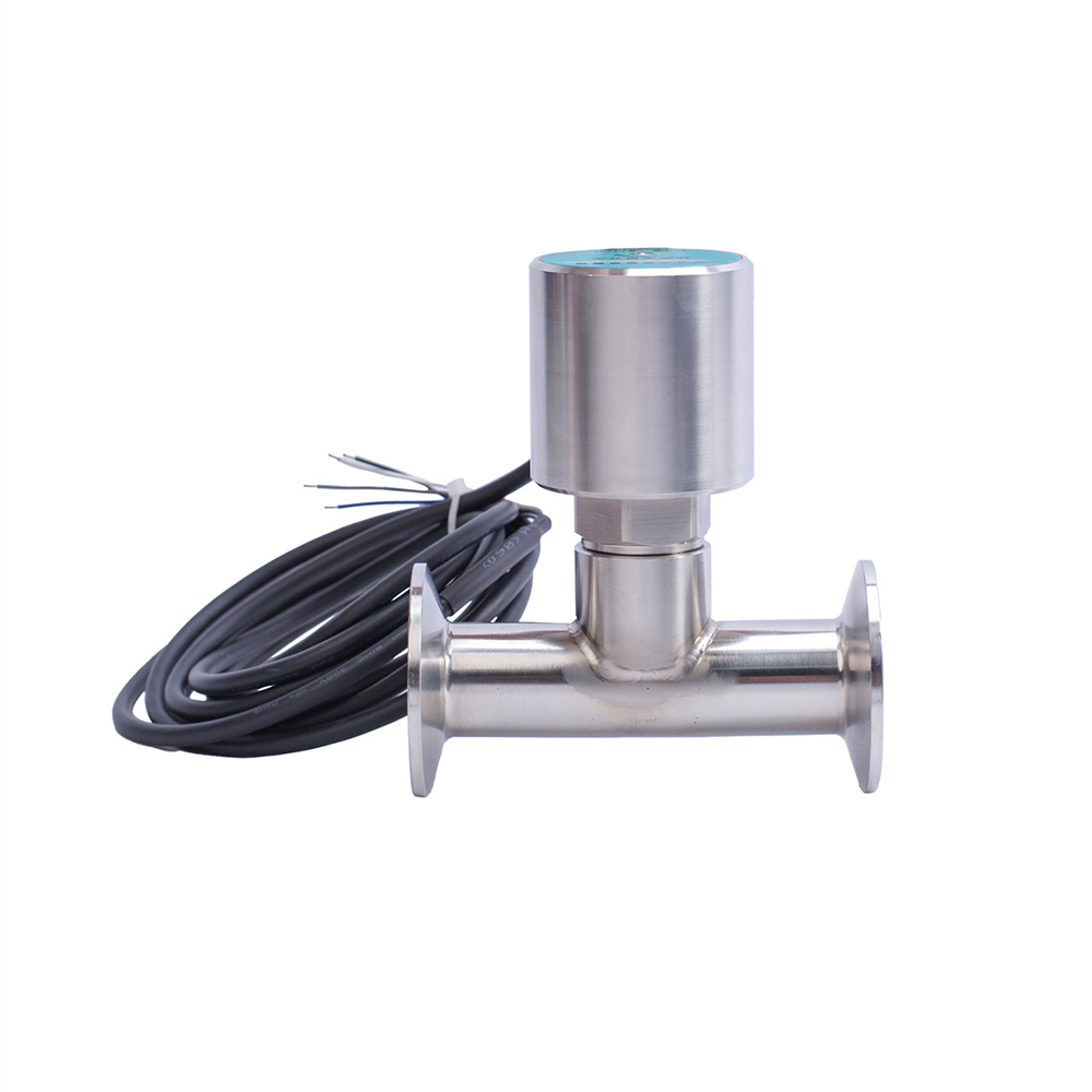
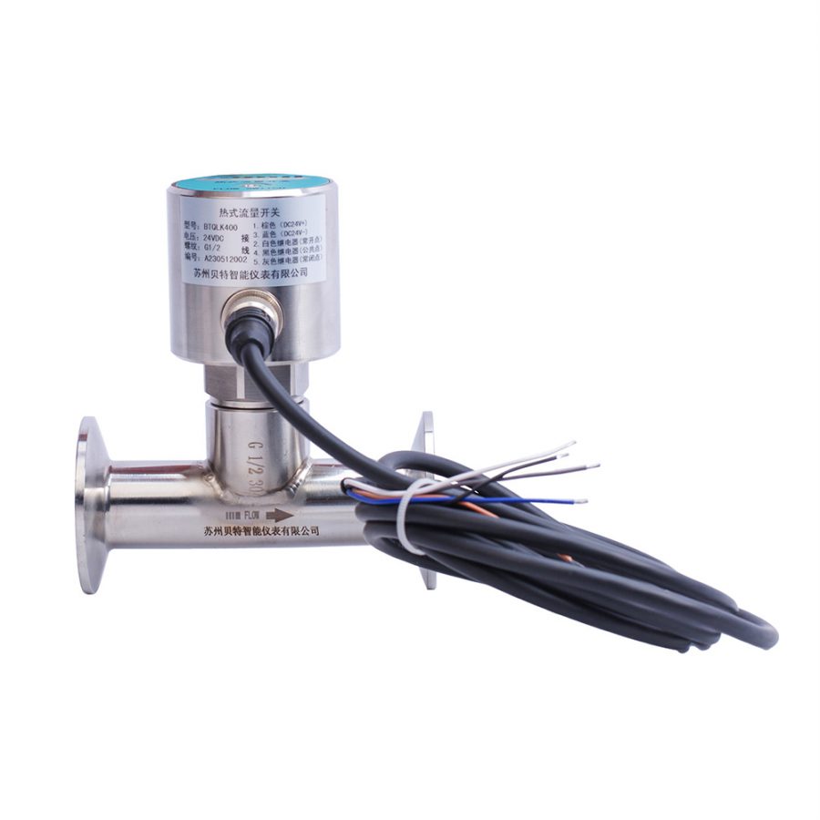
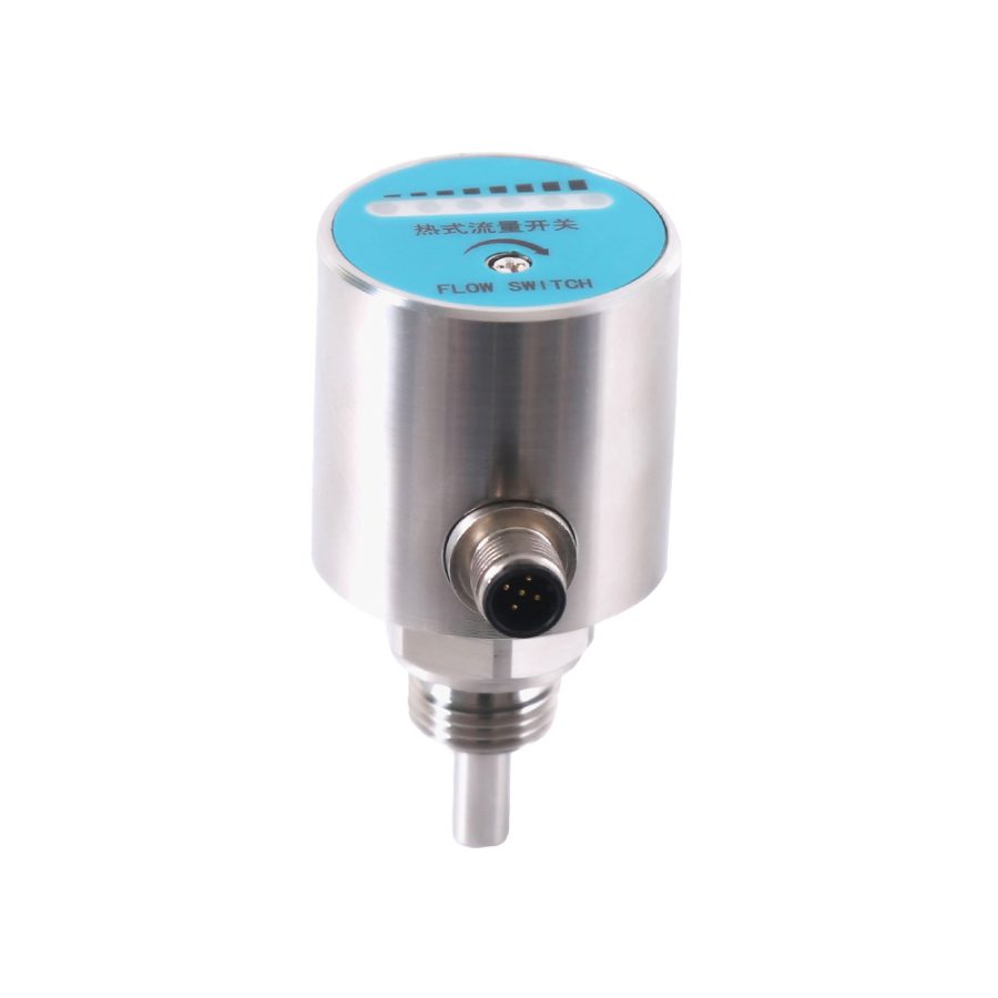
Appearance structure and electrical definition
The flow switch is connected by cable or connector. Its appearance is shown in Figure 1.
Structural dimension drawing:

Electrical definition: M12*1 aviation plug

Table 1 Electrical definition
Responsibility
Within one year from the date of shipment, our company will replace or repair products with quality defects due to material and workmanship problems free of charge; for product failures caused by non-quality reasons during use, our company will be responsible for repairs and only charge the material cost.