Working Principle
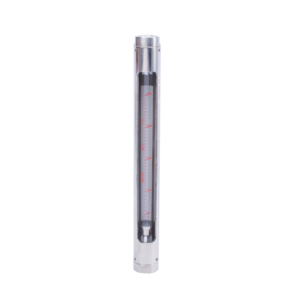
LZB glass rotor flowmeter is equipped with a float (rotor) that can move up and down in a vertical transparent cone tube. When the liquid passes through the cone tube from the bottom, it is throttled by the float, and a differential pressure is generated between the upstream and downstream of the float. The float rises under the action of this differential pressure. When the force that makes the float rise is equal to the combined force of the gravity, float and viscosity on the float, the float is in a balanced position. Therefore, there is a certain proportional relationship between the flow rate of the fluid flowing through the flowmeter and the rising height of the float, that is, the flow area of the flowmeter. The position height of the float can be used as a flow measurement.
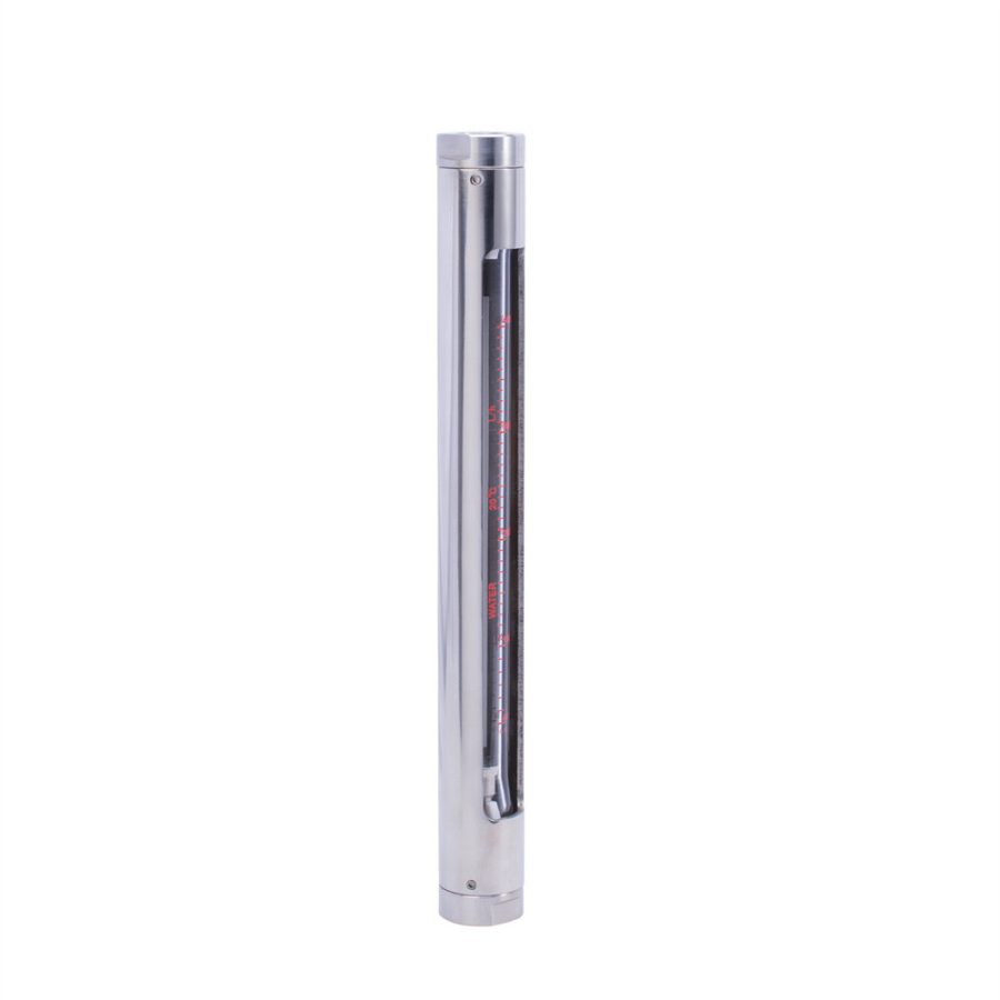
They are mainly composed of a conical glass tube, a float, an upper and lower base, an upper and lower stopper, a support plate, an outer cover, a sealing ring, etc. For flowmeters with a diameter of less than 10 mm, a pipe (soft or hard) connection is used, and a flow regulating valve can be provided. For flowmeters with a diameter of more than 15 mm, flange connection (JB78-59 cast iron flange) is used.
Product features
1. Accuracy: It can measure the tiny flow of liquid and gas. The lower limit of water flow can be measured to 0.4-4ml/min
2. Optional liquid contact materials: A variety of liquid contact materials are available: aluminum, brass, stainless steel, PP plastic, PTFE, FEP, etc.
3. Energy: No external power supply is required, and the flow indication is clear and intuitive.
4. Switch: It can be equipped with an alarm switch output.
5. Anti-corrosion: can measure corrosive fluids
6. Rich connection forms: a variety of process connection forms: thread, pagoda joint, ferrule, flange, etc.
Main applications
Sanitary metal tube rotor flowmeter has a simple structure, reliable operation, high accuracy and wide application range
-
Water treatment equipmentAtmospheric sampling flow monitoringGas flow monitoring in VOCs monitoring, sewage flow measurement
-
Laboratory applicationMetallurgy, power plants, printing and dyeing, coal mines, petroleum, drilling, food, beverages, brewing, drilling platforms and other industries are all used
-
Water treatment industryRO reverse osmosis, pure water flow measurement, distilled water flow measurement, injection water flow measurement
-
Photovoltaic industryMonocrystalline silicon industry, microelectronics industry, electroplating, electrolysis, PCB manufacturing industry
-
Electric power industryDesulfurization and denitrification of power plants, ammonia flow measurement, urea solution flow measurement
-
Chemical industryLiquid and gas process measurement and control system. Suitable for low flow rate, low viscosity, small and medium flow measurement and remote transmission of various fluids in all chemical industries
Working principle
The rotor material of the rotor flowmeter can be made of stainless steel, aluminum, bronze, etc.
The flow rate is measured based on the height of the metal tube float in the conical tube. The weight of the float is balanced by the pressure difference generated when the fluid passes through the gap between the float and the tube wall. The greater the flow rate, the higher the float is lifted, giving it a larger annular gap area, that is, the annular gap area changes with the flow rate, so it is generally called the area method. It is mostly used for the measurement of medium and small flow rates, and there are types equipped with electric remote transmission or gas remote transmission transmitters.
Technical parameters
Diameter DN
(mm) |
Model |
Measuring range |
Vertebral canal length (m) |
Accuracy level |
Allowable measured liquid state |
|
Water 20℃ |
Air |
LZB/LZJ |
LZB-()F |
Temperature (℃) |
Pressure |
|
20℃,10132SPa |
(MPa) |
|
2 |
LZB-2 |
0.4~4ml/min |
6~60ml/min |
160 |
1.5:2.5 |
2.5:4 |
-20~+120 |
≤0.4 |
|
0.6~6ml/min |
10~100ml/min |
|
1.0~10ml/min |
16~160ml/min |
|
1.6~16ml/min |
25~250ml/min |
|
3 |
LZB-3 |
2.5~25ml/min |
40~400ml/min |
|
4~40ml/min |
60~600ml/min |
|
6~60ml/min |
100~1000ml/min |
|
10~100ml/min |
160~1600ml/min |
|
4 |
LZB-4
LZB-4F |
(1~10)L/h |
(16~160)L/h |
|
(1.6~16)L/h |
(25~250)L/h |
|
(2.5~25)L/h |
(40~400)L/h |
|
6 |
LZB-6
LZJ-6F |
(2.5~25)L/h |
(40~400)L/h |
|
(4~40)L/h |
(60~600)L/h |
|
(6~60)L/h |
(100~1000)L/h |
|
10 |
LZB-10
LZJ-10F |
(6~60)L/h |
(100~1000)L/h |
2.5 |
≤0.6 |
|
(10~100)L/h |
(160~1600)L/h |
|
(16~160)L/h |
(250~2500)L/h |
|
15 |
LZB-15
LZJ-15F |
(16~160)L/h |
(0.25~2.5)m³/h |
350 |
|
(25~250)L/h |
(0.4~4)m³/h |
|
(40~400)L/h |
(0.6~6)m³/h |
|
25 |
LZB-25
LZJ-25F |
(40~400)L/h |
(1~10)m³/h |
|
(60~600)L/h |
(1.6~16)m³/h |
|
(100~1000)L/h |
(2.5~25)m³/h |
|
40 |
LZB-40
LZJ-40F |
(160~1600)L/h |
(4~40)m³/h |
430 |
|
(250~2500)L/h |
(6~60)m³/h |
|
50 |
LZB-50
LZJ-50F |
(0.4~4)m³/h |
(10~100)m³/h |
450 |
|
(0.6~6)m³/h |
(16~160)m³/h |
|
80 |
LZB-80
LZB-80F |
(1~10)m³/h |
(50~250)m³/h |
500 |
≤0.4 |
|
(1.6~16)m³/h |
80~400)m³/h |
|
100 |
LZB-100
LZB-100F |
(5~25)m³/h |
(120~600)m³/h |
|
(8~40)m³/h |
(200~1000)m³/h |
Instructions for use (installation)
12 steps are required to install a sanitary metal tube rotor flowmeter.
-
1. CleaningBefore installing the flowmeter, be sure to clean the welding slag and debris in the pipeline;
-
2. CalibrationThe vertical part of the flowmeter should be installed perpendicular to the ground and the inclination should not exceed 5°. Otherwise, it will affect the measurement accuracy.
-
3. PositionIn order to ensure the measurement accuracy of the flowmeter, a straight pipe section of no less than 10xDN should be added to the inlet end of the flowmeter, and a straight pipe section of no less than 5×DN should be added to the outlet end. When measuring, the regulating control valve should be installed downstream of the flowmeter.
-
4. ModelIf the measured medium is a large pulsating flow or two-phase flow, a buffer should be installed upstream of the flowmeter to reduce the pulsation and ensure that the flow of the medium is single-phase and stable. At the same time, it is recommended to use a damping type flowmeter.
-
5. Measuring mediumWhen the measuring medium is dirty or contains magnetic particles, it is recommended to install a filter or magnetic filter upstream of the flowmeter.
-
6. SupportThe installation of the flowmeter should be able to properly support the vibration of the pipeline or reduce the axial load of the flowmeter, otherwise the support of the fixed flowmeter should be increased.
-
7. MaintenanceIn order to facilitate the maintenance and repair of the flowmeter, the cleaning of the magnetic filter and the regular maintenance of the user pipeline, it is recommended to use a bypass pipeline as shown in the figure.
-
8. StabilityWhen the flowmeter is used for gas measurement, the working pressure in the pipeline should be no less than 5 times the pressure loss of the flowmeter, so that the flowmeter can operate stably and normally.
-
9. WiringBefore using the flowmeter with electric remote transmission and alarm limit switch, open the instrument cover and connect the wires correctly according to the wiring diagram.
-
10. StopperAccording to the warning sign in the instrument indicator, remove the stopper that prevents the float from vibrating during transportation, and use the instrument after restoration.
-
11. Turn on the flowmeterWhen turning on the flowmeter, since there is no pressure in the pipeline or the system has not reached the normal working pressure of the instrument, slowly open the control valve until the system is normal, and the instrument can be used, otherwise it is easy to cause the pointer to jump or the sudden impact of the float and damage.
-
12. User use When the user uses it, if the density of the measured fluid is different from that of water, or the parameters and working conditions of the measured gas are different from those specified by the manufacturer, the flow meter reading should be converted. The conversion method is shown in the appendix.